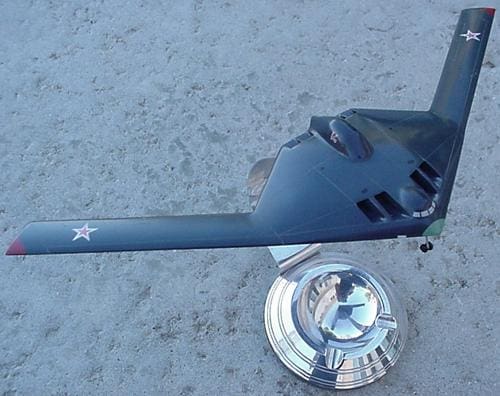
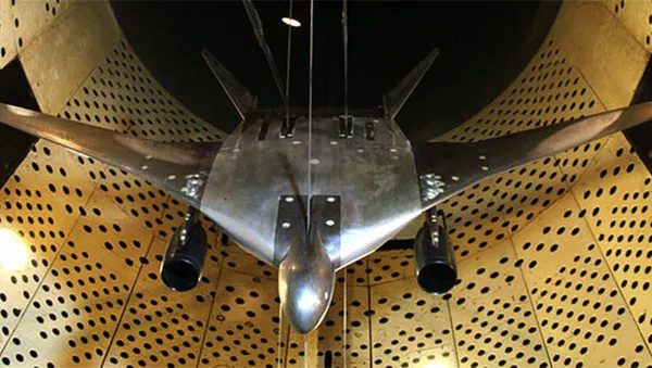
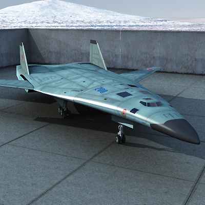
This patent MAY be related to PAK-DA, or not... but it is interesting nevertheless to consider the technical background
If related to the plane, first flight and/or disclosure should be relatively close.
AIRCRAFT ENGINE AIR INTAKEIPC
B64D 33/02(2006.01)
B64C 39/10(2006.01)
Application:
2021124506, 2021.08.18
Start date of the patent validity report: 2021.08.18
Application date: 2021.08.18
Published: 2022.03.16
Authors:
Bukharov Oleg Vladimirovich (RU)
Gurov Vyacheslav Fedorovich (RU)
Kataev Oleg Olegovich (RU)
Patent holders:
Public Joint Stock Company (PJSC) "Tupolev" (RU)
Documents cited in the search report:
WO 2010061071 A3, 03.06.2010.
RU 192918 U1, 07.10.2019.
RU 113238 U1, 10.02.2012.
RU 2033945 C1, 30.04.1995.
US 20200307789 A1, 01.10.2020.
FR 2619074 A1, 10.02.1989.
Illustrations 2
Report
The utility model relates to the aircraft industry and can be used in creating aircraft designs in which the engine air intake in the aircraft contains an inlet device (2) located near the leading edge (3) of the wing, connected to an air duct (4) passing inside the airframe to supply air to the engine. The air intake installation device is equipped with a rigid shell (6) of the air duct (4). The air duct (4) is located and fixed (5) inside this shell (6). The shell (6) is fixed (7) to the power elements (

of the airframe.
The technical result consists in achieving the rigidity and strength of the air duct under all flight modes and possible changes in angles of attack, as well as reducing the load on the airframe. 1 z. p. f-ly, 4 il.
Claim of the invention
1. An aircraft engine air intake containing an inlet device located near the leading edge of the wing, connected to an air duct passing inside the airframe, characterized in that it is equipped with a rigid duct shell, while the duct is located and fixed inside this shell, and the shell is fixed to the power elements of the airframe frame.
2. The air intake of the aircraft engine according to claim 1, in which the shell is made with the possibility of fixing to the power elements of the airframe frame using articulated nodes.
Description
The utility model relates to the aircraft industry and can be used to create aircraft structures.
According to the design scheme, engines in an airplane can be installed inside the airframe body, for example, according to the scheme disclosed in patent document US 2011240804 (A1); IPC B64D 27/12, published 06.10.2011. In this case, the air supply to the engine is made through a profiled air duct located inside the airframe.
The prototype of the utility model is a device for installing the air intake of a jet gas turbine engine installed in an aircraft made according to the "flying wing"scheme.
The air intake inlet device is located near the leading edge of the wing and is connected to the engine by an air duct passing inside the airframe (Application WO 2010061071 (A3); IPC: B64C 39/10; B64D 27/18; B64D 27/20; published 07.10.2010). Installation of the air intake is made in the form of an air duct directly attached to the structural elements of the airframe.
In the prototype, when the air flow passes, especially when changing flight modes or angles of attack, there are jumps in seals that cause additional loads on the walls of the air channel housing and it is necessary to perform local reinforcement of the housing, to avoid deformations that lead to loss of structural rigidity, affecting the stability of the air intake and, if the deformations exceed the permissible values, its strength.
When creating the utility model, the task was set to develop the design of the engine air intake in an airplane, in which air is supplied to the engine through a profiled air duct located inside the airframe, which ensures the rigidity and strength of the air duct under all flight modes and possible changes in angles of attack, as well as reducing the load on the airframe.
The problem is solved by the design of the engine air intake in an airplane containing an inlet device located near the leading edge of the wing, connected to an air duct passing inside the airframe, the air intake is equipped with a rigid duct shell, while the duct is located and fixed inside this shell, and the shell is fixed to the power elements of the airframe.
The technical result achieved in the implementation of the utility model is to achieve the rigidity and strength of the air duct in all flight modes and possible changes in angles of attack, as well as reducing the load on the airframe.
To unload the elements of securing the shell to the power elements of the airframe frame, the shell can be made with the possibility of fixing to the power elements of the airframe frame using hinge assemblies.
To explain the essence of the utility model, the following graphic materials are used:
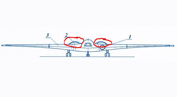
1 Aircraft, according to the utility model, front view;
2 Aircraft, in accordance with the utility model, top view;
3 Section A-A of Fig. 2;
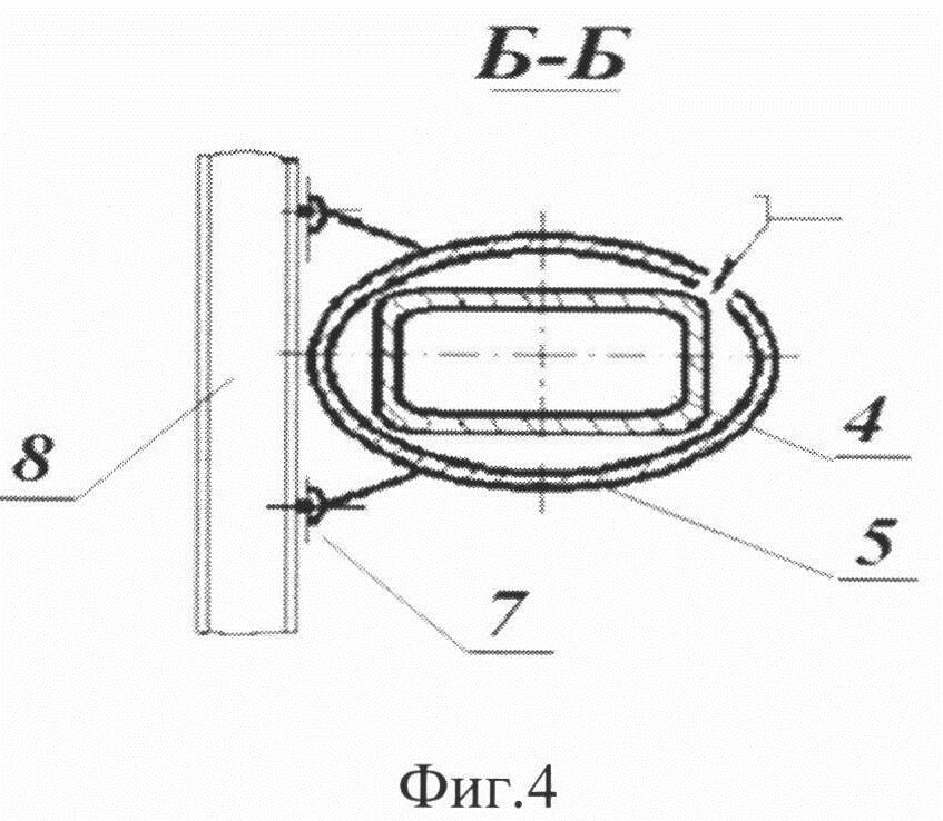
4 Section B-B of Fig. 2.
The utility model is used for the design of an aircraft in which the engine air intake contains an inlet device 2 located near the leading edge 3 of the wing, connected to an air duct 4 passing inside the airframe for supplying air to the engine. 1, 2).
The air duct 4 is made in the form of an air channel. The air channel profile is determined taking into account the optimal aerodynamic drag and achieving maximum internal braking of the air flow inside the air duct under the calculated flight modes. Devices can be stirred in the air channel to create an abrupt compaction of the passing air.
The air intake of the aircraft engine is equipped with a rigid shell 6 of the air duct 4 (Fig. 2, 3). The shell can be made of composite material. The air duct 4 is located and fixed 5 inside this shell 6. The shell 6 is fixed 7 to the power elements 8 of the airframe frame (Figure 4). The inner surface of the shell 5 covers the outer surface of the air duct 4. The air channel is fixed relative to the shell in order to exclude their displacement relative to each other.
Fixing 5 can be carried out by means of threaded connections, such as bolt-anchor nut, installed "in the strut", or by creating one-piece connections using welding, soldering, etc.
Fastening 7 of the shell 6 to the power elements 8 of the airframe frame, for example, to the spars or ribs of the wing can be performed using articulated units.
During the flight of the aircraft, air passes through the inlet device 2 and then is directed to the air duct 4, inside which the air flow is compacted.
When compacting the flow, local loads occur acting on the walls of the air channel, which, due to rigid fastening, are transmitted to the shell through the locking elements and do not cause deformation of the air channel profile, ensuring its rigidity and strength.
The air duct 4, fixed to the rigid shell 6, forms a structure that has joint inertial characteristics that absorb local and vibration loads that occur in the air duct.
If a load moment greater than the moment of inertia of the joint structure is created in the air duct, it is transmitted to the airframe through the fastening elements 7 of the shell 6 to the airframe and compensated for by its inertial characteristics.
Thus, the stability of the air intake and its strength are achieved in all flight modes and possible changes in angles of attack, as well as reducing the load on the airframe.
To unload the fastening elements 7 of the shell 6 to the airframe, they can be made articulated, using articulated units, while, in case of excessive local deformations when loading the joint structure of the air pipeline and the shell, instead of loading the junction point, a rotation will occur relative to the axes of the hinges in the direction of this moment. And, on the contrary, local deformations during the operation of the airframe frame will not lead to loading of the air channel

https://yandex.ru/patents/doc/RU209424U1_20220316
Thanks to stealthflanker


